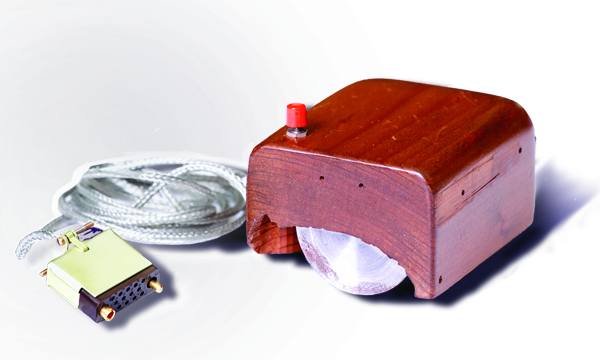
I'm assuming, naïvely again, that I can write a short blog post, but on past performance this isn't likely. I recently managed to get my Acorn Archimedes A3020 working again by converting a PS/2 mouse to a Quadrature mouse as early Archimedes' expect (see this blog post) and this has given me more of an interest in the system, particularly from a hardware viewpoint.
Wonderfully, I'm currently writing this on my MacBook Air M2, a 32-year later descendent of the ARM250 that powers that original A3020, so things have come full circle in a sense.
These early Arcs had a video chip called VIDC which supports 1, 2, 4 and 8-bit colour video modes at different resolutions, but for decades (probably even since the first review I saw in Personal Computer World August 1987), I was confused as to why the 8-bit colour mode was described as merely having a 64 colour palette with 4 tints instead of proper 8-bit RGB colours.
Why create something complex, which doesn't even do the job? What kind of terminology is 'tints'? How do you really use them?
The confusion deepened when I started to look into the VIDC hardware, because it never supported a 64-colour palette and some tints, instead it always supported a 16 x 12-bit colour palette for all modes, including the 8-bit colour mode. So, how did that work?
Standard VIDC Palette Entry
| Sup |
Blue |
Green |
Red |
| S |
B3 B2 B1 B0 |
G3 G2 G1 G0 |
R3 R2 R1 R0 |
The standard VIDC palette entry contains 4-bits for each component, Blue, Green and Red, oddly in that order than the conventional Red, Green, Blue order. In addition, it has a sort-of single alpha bit which can be used for
GenLocking. There are just 16 palette entries, so any one of them can be selected in 4-bits per pixel modes, but fewer of them are used in 1-bit and 2-bits per pixel video modes.
In 8-bit colour mode each 8-bit pixel is composed of a 4-bit palette entry and 4-bits which replace the four palette entry bits in bold above.
| Direct |
Palette |
| B3 G3 G2 R3 |
Palette 0..15 |
Although I've heard several claims that these ARM computers couldn't do proper 8-bit colour RGB, with 3 bits for Red, 3 bits for Green and 2 bits for Blue (human vision is less sensitive to blue). In fact we can immediately see that by defining the 16 palette entries so that they literally provide the other bits, we will get the equivalent of
RGB332 (really BGR233). This gives us:
| Direct | Palette |
|---|
| B3 G3 G2 R3 | B2 G1 R2 R1 |
Now we have 3 bits for Green and Red, and 2 bits for Blue. This means that in theory we have a proper 8-bit RGB mode; where we can freely select any one of the full range of 256 colours such a mode could describe. Note, we don't have a palette of 64 colours + 4 tints, we have a palette of 16 colours + 16 tints each and the palette can be assigned to provide the missing RGB bits.
How To Mess Up Palette Settings
A simplistic implementation of this would be to set all the remaining bits of the palette entries to 0, i.e. B1, B0, G0 and R0. This gives us the following palette:
| B2G1\R2R1 |
R2R1=0 |
R2R1=2 |
R2R1=4 |
R2R1=6 |
| B2G1=00 |
0x000 |
0x002 |
0x004 |
0x006 |
| B2G1=01 |
0x020 |
0x022 |
0x024 |
0x026 |
| B2G1=10 |
0x400 |
0x402 |
0x404 |
0x406 |
| B2G1=11 |
0x420 |
0x422 |
0x424 |
0x426 |
To re-emphasise, by itself this would give a very dull palette, because B3, G3, G2 and R3 are never set, but as described earlier, these bits are provided directly by the upper 4 bits of each 8-bit pixel. Consider three pixels: 0x03, 0x63 and 0x83. They all use the palette entry 3, which provides a medium-level red 0x006, but the second pixel would add a green component of 0xc making the colour: 0x0c6 and the third would add a blue component of 0x8 making the colour 0x806 (purple-ish). Combining the palette entries and modifiers then gives this 256 colour range:

Here, the colour range has been generated by a BBC Basic program running on an
Arculator, an excellent Archimedes
Javascript emulator. It looks pretty decent. It's shown in two formats, a literal RrrGGgBb view is on the left where each column represents the bottom 2 bits for green and both bits for blue while subsequent rows increment the top bit for green and the red component. However, it's easier to block out by splitting the full range into 4 quadrants of RrrGGg where each quadrant increments Bb. I also tried the same program on my real A3020, but this time in mode 28 as my monitor couldn't really cope with the non-VGA mode, mode 13 and got this:
I made a programming typo with the linear representation, but the quadrant version looks better than the emulator! This shows that the palettes really can generate a reasonable RGB332 colour range.
There is a minor problem in that the colours don't span the full colour range. Red and Green can only go to 87.5% of the maximum (0xe) and blue can only go to 75% of the maximum (0xc). The conventional way to address this is to replicate bits in the component, so the 8 proper levels for red and green would be: 0b0000, 0b0010, 0b0100, 0b0110, 0b1001, 0b1011, 0b1101, 0b1111. And for blue it'd be: 0b0000, 0b0101, 0b1010, 0b1111. And if the Arc had a full 256 colour palette, like every colour Mac from the Mac II onwards had, that's exactly what's done. Unfortunately, if you try to approximate this, you get a worse arrangement:

There are two obvious problem: on the right-hand spectrum, I've outlined how the Red=3 and Red=4 values look almost the same (as as do the Blue=1 and Blue=2, outlined on the left). This is because the difference is only 1 in each case: Red=3 translates as 0x7 (from the palette), and Red=4 translates as 0x8 (from R3); while Blue=1 translates as 0x7 (from the palette) and Blue=2 translates as 0x8 (from B3).
It turns out, then that the naïve palette assignment is the most evenly distributed one. And this brings us to the next observation:
A Hint On Tints: Exact 8-bit RGB Is Impossible
On a real 8-bit RGB palette, the blue values 00 to 11 scale into the full range of blue: 0x00 to 0xff, matching the same range as green and red where 000 to 111 scale to 0x00 to 0xff. However, the Archimedes palette (as alluded to earlier) scales unevenly: blue scales to 0xc0 while red and green scale to 0xe0. Also since neither scale to 0xff, the colours will be more dull.
Instead what we get is an effective 64-entry palette where we only consider the top two bits of each component: BbGGxRry + 4 green/red tints for each one: xy = 00, 01, 10, 11. And this explains why the Archimedes manual always describes 8-bit colours in those terms, but the choice of their default tints is different.
One of the other major problems with this palette is that you can only have 4 proper BGR233 greys: 0x00, 0x52, 0xa4 and 0xf6. The slightly brighter colours: 0xf7, 0xfe and 0xff are off-white, pink, green and yellow tints. Ironically, proper RGB332 can only manage two greys! Consider RGB332 represented by 256 x 12-bit BGR palette entries or 256 x 24-bit BGR palette entries. Black is RGB332=0x00 which maps to 0x000 in the 12-bit palette and {0x00, 0x00, 0x00}. The next closest is Red=Green=2, Blue=1. This is 0x544 in the 12-bit palette and {0x55, 0x49, 0x49} in the 24-bit palette - both slightly blue. Then Red=Green=4, Blue=2, which is 0xa99 in the 12-bit palette and {0xaa, 0x92, 0x92} in the 24-bit palette, again, both slightly blue; then Red=Green=7, Blue=3 which is 0xfff in the 12-bit palette and {0xff, 0xff, 0xff} in the 24-bit palette.
In both of those cases, even the 24-bit palette is 16% out from a grey which is distinguishable to the human eye.
The Alternative Palette Approach
The conventional VIDC 8-bit palette with 64 base colours and 4 tints I now understand will look something more like this:
| Direct |
Palette |
| B3 G3 G2 R3 |
B2 R2 T1 T0 |
Where T1 and T0 represents the tints of white, which get added to all of B1B0, G1G0 and R1R0. This kind of palette would contain these entries:
| B2R2\Tint |
0 |
1 |
2 |
3 |
| B2R2=00 |
0x000 |
0x111 |
0x222 |
0x333 |
| B2R2=01 |
0x004 |
0x115 |
0x226 |
0x337 |
| B2R2=10 |
0x400 |
0x511 |
0x622 |
0x733 |
| B2R2=11 |
0x404 |
0x515 |
0x626 |
0x737 |
This time we essentially have 4 dimensions to consider: Blue<2>, Green<2>, Red<2> and Tint<2>, I thought a recursive arrangement would be clearest, but it turns out that a semi-linear arrangement is:
Here, 4 horizontally adjacent blocks are the tints and then each horizontal block of 4 is the red component; while 4 vertically adjacent blocks are the blue component and each vertical block of 4 is green.
Trying to process images in this convention is challenging, because (as we'll see in the next section) it's hard to calculate how to dither each component, because they aren't truly independent and can't be, because there are really only 3 primaries (Red, Green, Blue), but four components. For example, it's easy to see that the top left and bottom right tint groups are actual greys, but harder to see that there's two other grey blocks (which I've outlined). This means we can't independently adjust tints against RGB.
Nevertheless, this convention has a several advantages over RGB332:
- The RGB primaries are all evenly distributed, they get 2-bits each.
- There are 16 levels of grey, which means that anti-aliased black text on a white background (or its inverse) can be done pretty well.
- There's a brighter range because it goes up to 0xfff.
- Human vision is more attuned to brightness than colour, which is why the HSV colour model is effective, so it's possible that this convention can represent images that perceive better to us.
Dithering
Even though we only have 256, imperfect base colours in our quasi-BGR332 palette, we can employ a standard technique to mask this, called dithering. I wanted to generate the inner surface of an RGB cube (where black is the bottom, left, front corner and white is the top, right, back corner) to show how we can generate fairly smooth colour transitions, by applying a fairly standard Floyd-Steinberg dither.
There's a really good blog post on dithering
here, which covers far more forms of dithering that the ordered and FS dithering I knew about. FS dithering works by scanning the original image in raster order and then computing the error from the closest colour we can generate and then propagating the error to the immediate pixels on the right and below (or right and above).
In fact we can compute all of this by just maintaining a full-colour error array for a single row + the single pixel to the right.
3D Projection
So, dithering is fairly simple, but the 3D projection was actually fairly complex, because I couldn't just draw an image in normal 3D space, I had to scan the image; translating row and column pixels into (x,y,z) coordinates for the cube, culling pixels outside the cube and then calculating the furthest pixel at each of these points. Then x corresponds to red, y corresponds to green and z corresponds to blue. This involved quite a number of mistakes! To make the 3D calculations simple I generated an orthogonal projection where z=column*4/5+row*3/5; which is essentially a 3:4:5 triangle and avoids having to compute floating point maths nor square roots. The hacky calculations work as follows:
First we want to transform from (column, row) space (the screen coordinate) to (x,y,z), where y is down/up and z is depth. (0,0) is easy, it's (0,0,0) and any coordinate along the c axis is easy it's (c,0) => (c,0,0). As we go up rows, the beginning of the cube starts slightly further to the right and because of the projection, we know that (c, r)=(4,3) is also easy, it's (0,0,5). Similarly, any ratio where r=3c/4 is also (0, 0, 5c/4). When we're to the left of that axis, we're part of the left plane, so we need to draw that, and then the column calculation is the smallest, because e.g. (0, r) => (0, 0, 5r/3) > (0,0,5c/4) since 5c/4 is 0, but when we're to the right of that axis, the row calculation is the smallest. The back face is determined by the maximum depth of 255, so we simply limit the depth to that to generate it. (x,y,z) then map directly to (r, g, b).
In the end, I generated this Colour cube on the emulator:
It looks fairly smooth, but we can see some banding. Real-life images aren't smooth, so they don't tend to exhibit the same kind of artefacts.
Conclusion
Early, colour microcomputers had many compromises because of speed and memory limitations. Many of them used Palettes (Atari 8 and 16-bit, Acorn BBC and Archimedes, Macintosh II, Apple ||gs, PC EGA and VGA modes, the Amiga..) to provide a wider colour range than possible given the number of allocated bits per pixel and some used other tricks such as colour attributes which allowed a full colour range across the screen with a low colour boundary resolution (e.g. VIC-20, ZX Spectrum, Commodore 64, also Amiga HAM mode). As frame buffer memory approached 64kB or above, during the late 80s, it became possible to provide passable 8-bit true colour video in home computers. The early colour Macintosh II,
PC MCGA and Archimedes computers fall into this category. They all use palettes, except that the Mac II and MCGA mode have 256 entries, each of 24-bits (or 18-bits in the case of MCGA).
The Archimedes A3020 inherits its graphics from its Atari ST / Commodore Amiga era incarnation with a limited 16 entry x 12-bit palette and a cheap hack to support a 'true' colour mode. The alternative, a proper 256 entry palette would have required a relatively costly 384 bytes of Palette RAM (+18K transistors) or a late chip redesign and a later or more expensive release for the integrated ARM250 chip[1].
Acorn's tendency to be technically pedantic I think, is what lead them to claim this mode is really 64-colours + 4 tints rather than a decent approximation to RGB332 from 16-base colours + 16 palette entries. RGBT2222 has some advantages, but RGB332 (really BGR233) makes most sense as a colour range, because all the others lead to either greater banding or a less coherent relationship between pixel bits and primary components. It turns out that it's possible to achieve a reasonable approximation to RGB332 on an Archimedes.
Notes [1]: ARM250 die from the Microprocessor Report linked earlier. The ARM CPU itself requires 29K transistors, so adding 18K transistors to VIDC would have resulted in a notable increase in size and cost for the 100K transistor, $25 chip.