After an embarrassing amount of work I managed to convert a PS/2 mouse into a quadrature encoding mouse for my Acorn Archimedes A3020.

A Mini-Mouse History


I know I could have bought a USB to quadrature encoded mouse adapter (from here on, QE mouse, because I don't like the term Bus-mouse), but that seemed like a cop-out, so instead I decided to make things as painful as possible. The first stage was to cut out the blobtronics that made it a PS/2 mouse.

Then I added some pull-down / level-shifting resistors to see if the A3020 would recognise it as valid values but it didn't. Then I went through a long process of getting an Arduino to recognise the analog voltages from the phototransistor (yep, I also know I could use a Schmitt-trigger buffer chip) and write a small program to actually process them into quadrature encoded X and Y grey code (Ref: Dir are 00, 01, 11, 10, 00... for forward/up and 00, 10, 11, 01, 00.. for backward/down). It turned out it wasn't very digital!

I figured I could solve the problem in software using a small MCU that would fit in the mouse, so I chose an ATTINY24, a 14-pin AVR MCU with 8 ADC 10-bit channels and 4 other digital IO pins. I used a simple hysteresis algorithm: it first figures out the range of values it can get from the phototransistors; then allows a bit more time to see if the range is bigger; then once it's interpreted any given state, the ADC values have to change by 2/3 of the range to flip into the next state.
I went through quite a bit of a debugging process, because obviously when you go from a fairly lush environment like an Arduino (plenty of libraries, plenty of IO pins, lots of code space and relatively abundant RAM (2kB ;) )) to an ATTINY24 (2kB flash, 128 bytes of RAM, just 12 IO pins) and then stick it in a mouse, the fewer opportunities you have for debugging - and you can't even use an LED inside a trad, ball mouse, because ta-dah, you won't see it! So it's best to debug as much as possible in simulation, before you take the final step. In fact the program only ended up being about 906 bytes, because 'C' compiles pretty well on an 8-bit AVR.
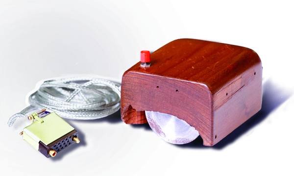
I made a lot of mistakes at pretty much every stage - but amazingly getting the mouse directions inverted wasn't one of them :) . I started with 10K resistors for the phototransistors, but then ended up deducing 15K was best (22K || 47K) so that was 8 resistors! When soldering the analogue connections to the AVR I was out by one pin all the way along, because from the underside, I mistook the decoupling cap pins for the Pin1 and Pin 14 of the AVR. I had to desolder the phototransistor connections to the main cable - which I'd been using when analysing on the Arduino; then solder up the photo transistors to the analog inputs and then the digital outputs to the original wires. I tried to keep the wires no longer than they needed to be because it was cramped in there, but I ended up making the Y axis analog wires just 1mm too short (because, d'uh they get a bit shorter when you strip them and feed them through a PCB) so they had to be redone. Because there were a lot of wires I needed to glue them down as otherwise the casing wouldn't close, and I was particularly concerned about the phototransistor wires getting caught in the Y axis wheel, but then I glued them down directly underneath that wheel so it couldn't clip into place! I also glued the grey and green wires running up the right so that they got in the way of the case closing - so all of these had to be very carefully cut out and moved. Near the end I remembered I had to add a 10K resistor between reset and power so that the MCU would actually come out of reset and execute code! I also had to add an input signal, to software switch the Y axis inputs to the X axis grey code, because the only header I could find to fit the mouse cable plug for testing didn't leave room to test both X and Y grey codes! Hence what looks like an extra button!
Finally I connected it all up, glued the board and wires down (after correcting the locations) and got: A BIG FAT NOTHING! I thought maybe I'd messed up the analogue ranges and retried it with a different range and that didn't work. Then I realised I could output debug serial out of one of the grey code outputs to the Arduino and see what the ATTINY was reading! Bit-banged serial code can be very compact!
void PutCh(uint8_t ch)
{ // (ch<<1) adds a start bit in bit 0 and |0x200 adds a
uint16_t frame=((uint16_t)ch<<1)|0x200; // stop bit.
do {
if(frame&1) {
PORTB|=kSerTxPin;
}
else {
PORTB&=~kSerTxPin;
}
frame>>=1;
_delay_us(52.083333-11/8); // 19200 baud.
}while(frame); // & after the stop's been shifted out,
// the frame is 0 and we're done.
}
Before I tried it, I did a sanity check for power and ground only to find I hadn't actually connected up VCC properly!!!! I'd forgotten the final stage of solder-bridging the decoupling cap's +ve lead to Pin1 of the AVR and I ended up ungluing everything so I could see underneath.
But when I fixed this and packed it all back in the case: It Worked! I tried reading the digital outputs at the end of the cable on the Arduino and when I was satisfied (which only took a few minutes of testing) I decided to hook it up to my A3020 and hey-presto! I have a working QE Mouse!
I had been a bit concerned that doing analog sampling wouldn't be fast enough and so my algorithm has a heuristic whereby if it sees a jump of 2 transitions (00 <=> 11 or 01 <=> 10) it assumes it's a single step in the same direction as before. I could manage about 20K x 4 samples per second, but a little maths shows this will be fine, because a full 640 pixels on the Arc's screen can be sampled OK if you cover it in about 3.2ms and clearly we don't do that.
!Paint, which is like, 96kB I think! It's terribly unintuitive though! Note on the video that a 12MHz ARM250 can drag whole, 4-bpp x 640x480 windows around rather than just outlines! Note also the Taskbar, which was standard on the Archimedes before Windows 95, or Mac OS X (NeXT step had a floating Dock).
Here, again is the link to the project and source code.
No comments:
Post a Comment